


Engineering and Technical Guide for Coolant Distribution Units (CDUs): Architectural Design, Component Trade-offs, and O&M Practices
Driven by the explosive growth of generative AI and large-scale model training workloads, the power density of data center racks has entered a new era of rapid expansion. Modern ultra-high-density computing racks (such as NVIDIA GB200 and AMD MI350 platforms) have already exceeded 120kW per rack in power consumption.
Traditional air cooling architectures are increasingly reaching their physical heat dissipation limits. Under these circumstances, the Coolant Distribution Unit (CDU) has become an indispensable fluid management and heat exchange hub for modern direct-to-chip liquid cooling infrastructures.
This article provides a comprehensive analysis of CDU applications in AI computing clusters from multiple perspectives, including engineering implementation, core component selection, system configuration, and daily operation and maintenance.
1.0 Why Do AI GPUs Depend on CDUs Instead of Air Cooling?
Traditional air cooling systems rely on air as the heat transfer medium. Due to air’s low specific heat capacity and poor thermal conductivity, the maximum cooling capability of a single rack is typically limited to approximately 10kW–20kW.
For GPU clusters consuming hundreds of kilowatts of power, air cooling is unable to remove the intense instantaneous heat generated by modern processors quickly enough.
However, while direct-to-chip liquid cooling dramatically improves heat removal capability, it also introduces several engineering challenges:
- Microchannel blockage:
The micron-scale internal channels inside cold plates are highly susceptible to clogging caused by particles or contaminants in the coolant. - System corrosion risk:
Long-term exposure of coolant to oxygen or incompatible metals may result in chemical oxidation and pipeline corrosion. - Condensation and short-circuit risks:
If coolant supply temperature is improperly controlled and falls below the room dew point temperature, moisture condensation may occur on electronic components. - Coolant degradation risks:
Changes in coolant pH value and electrical conductivity directly affect the long-term reliability of the cooling system.
The core engineering value of a CDU is precisely to address these challenges.
Through an integrated design featuring:
- primary-side / secondary-side coolant circuit isolation,
- high-precision dynamic temperature control,
- multi-stage filtration,
- intelligent leakage interlock protection,
the CDU achieves the optimal balance between high cooling performance and long-term operational reliability.
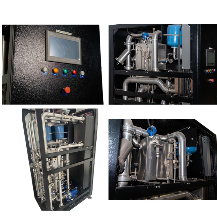
2.0 What Is a Coolant Distribution Unit (CDU)?
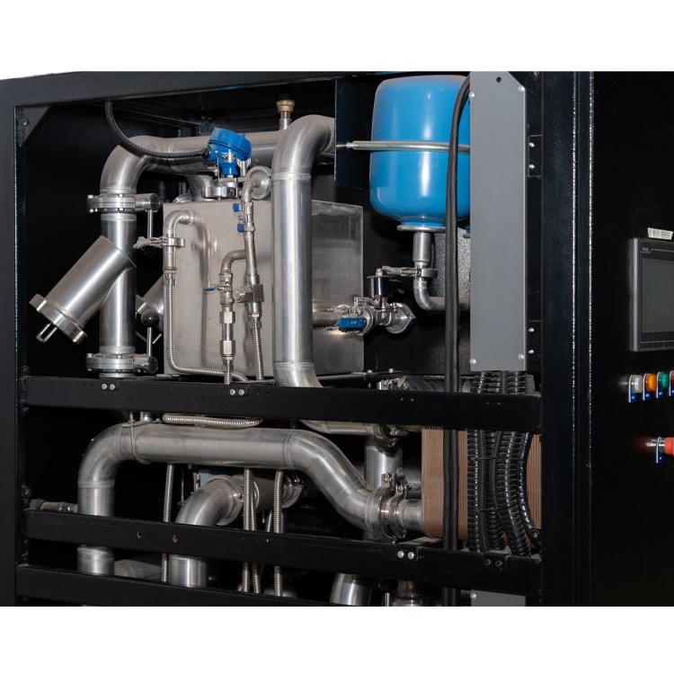
From a mechanical and thermal engineering perspective, a CDU is the central fluid control platform connecting the IT equipment cooling loop with the facility cooling infrastructure.
Its fundamental design philosophy is based on two principles:
Isolation and Precision Control
Through physical separation, the CDU prevents facility water with potentially inferior water quality from directly entering the highly sensitive and narrow cooling channels inside server cold plates.
A complete standard CDU integrates six major subsystems:
- Heat Exchange System (Plate Heat Exchanger, PHE)
Transfers heat efficiently between the secondary-side IT cooling loop and the primary-side facility water loop. - Power Drive System (Variable-Speed Pump Assembly)
Maintains stable coolant circulation on the secondary side and ensures proper supply pressure balance between racks. - Distribution Manifold System
Distributes coolant evenly from the main supply line to individual branch circuits. - Fluid Regulation System (Valves and Flow Meters)
Dynamically adjusts coolant flow according to real-time GPU thermal load. - Multi-stage Purification System (Filters)
Captures contaminants and protects cold plate microchannels from particle erosion and blockage. - Automation Control Architecture (PLC and Sensors)
Monitors temperature, pressure, flow rate, and leakage conditions while communicating with higher-level BMS/DCIM systems.
3.0 Core CDU Components: Engineering Trade-offs
3.1 Plate Heat Exchanger (PHE)
The brazed stainless-steel plate heat exchanger is the thermal transfer core of a liquid-to-liquid CDU.
During selection, engineers must carefully balance size, cost, and heat dissipation performance.
Oversized Heat Exchanger:
- Increases initial equipment procurement cost.
- Occupies valuable data center space.
Undersized Heat Exchanger:
- Provides insufficient heat transfer area.
- Cannot handle peak GPU thermal loads.
- May trigger processor thermal throttling protection.
Key design parameters include:
- Target total cooling capacity
- Approach temperature between the two fluid sides
- Maximum allowable pressure drop
- Pump power consumption evaluation
- Future computing expansion margin
3.2 Variable-Speed Redundant Pump System
Fixed-speed pumps can cause unnecessary power consumption and excessive fluid shear under low-load operating conditions.
By adopting variable-frequency drive (VFD) controlled variable-speed pump assemblies, the CDU can dynamically adjust pump speed according to real-time chip thermal power demand, maintain constant system pressure, and significantly reduce operational energy consumption.
Common pump architecture comparisons and engineering trade-offs:
Before system deployment, engineers must conduct pump pressure response testing under both full-load and partial-load conditions to ensure smooth primary/backup switching logic.
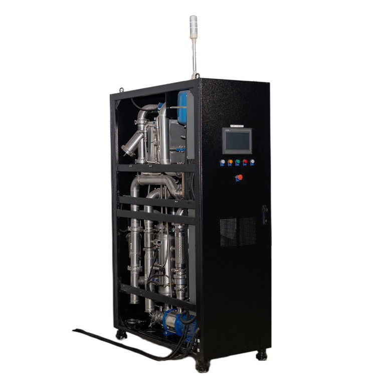
3.3 Manifold Piping and CNC Pipe Punching / Flanging Processing Technology
Traditional machining methods and welded tee fittings can create internal turbulence, while numerous welding points may experience stress aging and leakage risks under long-term thermal expansion and contraction cycles.
Modern Engineering Selection:
The industry increasingly adopts CNC precision punching and flanging technology, which directly forms seamless branch outlets from the main pipe wall.
This integrated manufacturing process provides:
- Extremely smooth internal flow passages.
- Reduced hydraulic resistance.
- Fewer welding points.
- Improved pressure resistance.
- Higher fatigue durability of connection structures.
For piping materials, high-grade stainless steel such as 316L stainless steel or dezincification-resistant copper should be preferred to minimize electrochemical corrosion risks.
3.4 Valve, Balancing, and Flow Measurement Components
Electric control valves, static balancing valves, and high-precision flow sensors work together to ensure accurate coolant distribution according to actual cooling demand.
If flow distribution is unbalanced, multiple rack rows may experience localized thermal accumulation, reducing the overall computing efficiency of the AI cluster.
3.5 Filtration System
- 50 micron (μm) filter element:
The industry-standard balanced configuration for AI computing applications, achieving the optimal compromise between contaminant removal efficiency and hydraulic resistance. - 25 micron (μm) filter element:
Provides higher cleanliness protection but creates greater flow resistance and tends to clog more quickly. - 100 micron (μm) filter element:
Reduces pump load but cannot effectively prevent smaller metal particles that may damage cold plate microchannels.
Field Engineering Experience:
During the first 1–3 months after commissioning a newly constructed liquid cooling system, residual welding debris and machining particles inside the piping system are gradually released. During this period, filtration inspection and replacement frequency should be increased.
3.6 Sensors and PLC Control Architecture
The system integrates:
- temperature sensors,
- pressure sensors,
- differential pressure sensors,
- flow sensors,
- distributed rope-type or spot-type leakage detection cables.
An industrial-grade PLC serves as the central controller, executing real-time PID regulation.
When abnormal pressure drops or leakage events are detected, the system can rapidly trigger alarms and execute interlock actions such as:
- closing isolation valves,
- stopping pumps,
- notifying upper-level monitoring systems.
4.0 Two Major CDU Configuration Types
Based on the heat rejection method of the primary-side heat sink, CDUs are mainly divided into two categories:
1. Liquid-to-Liquid CDU
Principle:
The primary side connects to the facility chilled water or cooling tower water loop, while the secondary side connects directly to the IT cold plate cooling circuit.
Characteristics:
- Extremely high heat removal capability.
- Capacity ranging from several hundred kilowatts to megawatt scale.
- Very high energy efficiency ratio (COP).
- Widely used in newly constructed large-scale and hyperscale AI data centers.
2. Liquid-to-Air CDU
Principle:
The secondary side circulates liquid coolant, while the primary side rejects heat through air-cooled coils and fan assemblies into the surrounding environment.
Characteristics:
- No requirement for external facility water piping infrastructure.
- Flexible deployment.
- Suitable for retrofit projects in existing data centers or edge computing sites.
However, maximum rack power density is limited by room ventilation capability.
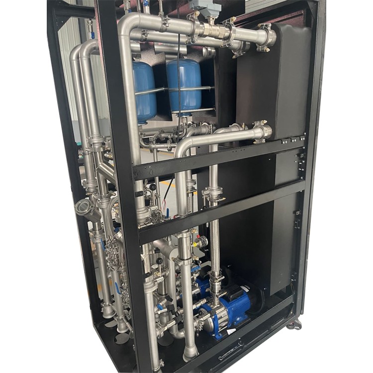
5.0 CDU Installation Locations and Deployment Architectures
1. In-Rack CDU
A compact CDU installed directly inside an individual server rack.
Advantages:
- Shortest coolant transport distance.
- Extremely fast thermal response.
- Ideal for single-rack high-density cooling.
Limitations:
- Requires dedicated internal rack maintenance space.
- Each rack requires individual CDU allocation.
Typical application:
Single rack cooling around 100kW class.
2. In-Row CDU
A standalone CDU installed alongside server racks within the same row.
Advantages:
- Centralized maintenance.
- Can support approximately 6–20 adjacent racks.
Challenges:
- Hydraulic balancing between multiple racks.
- More complex branch piping management.
3. Centralized CDU
Large industrial skid-mounted CDU systems installed in dedicated mechanical rooms or facility support areas.
Advantages:
- Centralized operation and maintenance.
- Suitable for entire data halls.
- Supports MW-scale AI computing clusters.
6.0 CDU vs CRAC vs CRAH vs Chiller Concept Comparison
To clearly understand the role of CDU within the overall data center cooling architecture, the following comparison summarizes its differences from traditional data center cooling equipment:
Summary:
CRAC and CRAH systems are designed only for air cooling and cannot directly interface with server chip cold plates.
Chiller systems provide building-level cooling sources.
The CDU is the only dedicated isolation and distribution platform directly serving high-density IT liquid cooling cold plate systems.
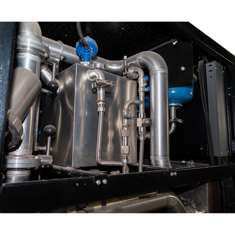
7.0 How to Select the Appropriate CDU Capacity
CDU selection must be accurately calculated according to the maximum thermal output and hydraulic characteristics of the rack cluster.
8.0 Core Cooling Loop Design Guidelines
8.1 Coolant Chemical Management
The secondary cooling loop typically operates with:
- high-purity deionized water (DI Water)
or - diluted water-ethylene glycol (WEG) mixture
with carefully controlled corrosion inhibitors.
Monitoring Requirements:
Operations teams should regularly sample and analyze:
- pH value,
- electrical conductivity,
- chloride ion concentration.
Risk Prevention:
Excessive chloride concentration may cause:
- pitting corrosion of stainless-steel plate heat exchangers.
An excessively low pH value may accelerate:
- copper cold plate corrosion.
All standard CDUs should be equipped with dedicated coolant sampling ports.
8.2 Condensation (Dew Point) Control
To prevent condensation forming on chips and motherboard surfaces, the CDU control system must ensure that:
The secondary-side coolant supply temperature always remains above the room dew point temperature.
The typical design margin is:
2℃–3℃ above dew point temperature.
When abnormal humidity conditions occur in the data center environment:
The PLC automatically:
- adjusts primary-side valve opening,
- increases supply water temperature,
- prevents condensation risk.
8.3 Flow and Pressure Planning
During pipeline design, engineers must control maximum coolant velocity:
Typically below 1.5–2.5 m/s
to prevent:
- pipe wall erosion,
- excessive hydraulic loss.
At rack connection points, engineers should use:
Low-resistance, dry-break quick couplers
to reduce localized pressure losses.
8.4 Multi-Layer Leakage Mitigation
To provide maximum protection for expensive GPU hardware, CDU systems should incorporate multiple leakage protection layers:
1. Physical Layer
Includes:
- dry-break quick connectors,
- rack-level manual/electric isolation valves.
2. Monitoring Layer
Includes:
- distributed leakage detection cables installed beneath racks and pipelines.
3. Logic Layer
When PLC receives:
- moisture detection alarms,
- leakage signals,
the system automatically:
- stops pumps,
- closes coolant supply valves,
- triggers emergency notifications.
9.0 Daily Field Maintenance Schedule
To ensure long-term stability and reliability of the CDU and secondary cooling loop, the following standardized maintenance schedule is recommended:
Daily
Perform visual inspection of:
- manifold connections,
- quick-disconnect couplings,
- piping interfaces.
Confirm there are no signs of:
- leakage,
- seepage,
- abnormal moisture.
Monthly
Inspect:
- filter differential pressure,
- filter physical condition.
During initial operation of newly installed systems:
- clean or replace filter elements more frequently.
Quarterly
Perform secondary coolant sampling and chemical balance testing:
- pH value,
- electrical conductivity,
- corrosion inhibitor concentration.
Every Six Months
Conduct functional testing of:
- automatic pump failover switching,
- leakage detection alarms,
- safety interlock functions.
Every 2–3 Years
Perform:
- complete flushing of the secondary cooling loop,
- replacement of coolant,
removal of accumulated microscopic sediments.
10.0 Future Industry Development Trends
10.1 Short-Term Development (Near-Term Commercial Technologies)
1. Warm-Water Cooling Architecture
By increasing primary-side supply water temperature:
32℃–45℃
warm-water cooling architectures can maximize the utilization of outdoor natural cooling sources (Free Cooling), significantly reducing the operating time of mechanical chillers.
2. AI Predictive Flow Control
By combining:
- neural network models,
- GPU workload prediction,
- real-time thermal analysis,
future CDU control systems can proactively adjust variable-speed pump output, eliminating temperature response delays.
3. Prefabricated Modular Skid Design
Factory-integrated and factory-tested CDU skid systems enable:
- rapid deployment,
- standardized installation,
- modular expansion.
This allows future data centers to be assembled using a building-block approach.
10.2 Long-Term Evolution Trends
1. Digital Twin Integration
By creating complete thermal and fluid simulation models of cooling infrastructure, digital twin systems will enable:
- real-time fault prediction,
- dynamic cooling optimization,
- intelligent operational decision-making.
2. Complete Waste Heat Recovery Systems
Future liquid cooling infrastructures will capture high-quality server waste heat and reuse it for:
- district heating,
- greenhouse applications,
- domestic hot water production.
3. Simplified Hybrid CDU Architecture
A future generation of CDU hardware may support multiple cooling technologies within a unified platform, including:
- direct-to-chip liquid cooling,
- immersion cooling,
- traditional air cooling.
This will enable flexible cooling resource allocation across heterogeneous computing environments.
What coolant fluid circulates inside a CDU’s secondary loop?
How frequently should CDU filter cartridges be swapped out?
What is the typical maximum cooling capacity of different CDU styles?
Does every individual AI rack require its own dedicated CDU unit?
Leave A Message
If you are interested in our products and want to know more details, please leave a message here, we will reply you as soon as we can.